About
This machine monitor and controls two pumps connected to it, according to different water levels. Indicators and manual user testing allow the consumer to use this more efficiently. It is easy to install, maintain, and replace(pumps) by following the instructions mentioned in the user manual. In general, this project will be helpful for house owners (especially one in the countryside) whose basement flooded with water because of a pump connected in the basement not functioning properly.
Abstract
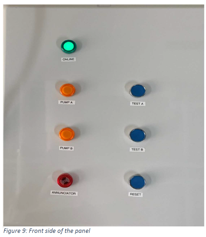
Furthermore, on the front side of the panel, four LED indicators (ONLINE, PUMP A, PUMP B, ANNUNCIATOR) and three push button switches (TEST A, TEST B, RESET) exists, which make this device more user friendly. After installment, the user can connect the pump and adjust current tripping points according to the steps mentioned in this report.
Introduction
Functional Overview
Fuse
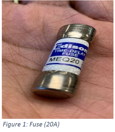
Fuse's job is to protect the System and part of the System from overload. There are three fuses used in this project. The first connected next to supply (120 VAC) is called primary fuse (Figure 1: Fuse (20A)), which protects the entire system, and the other two fuses before contactors (A & B) is known as secondary fuse which saves individual pump (A/B) system.
Water Levels
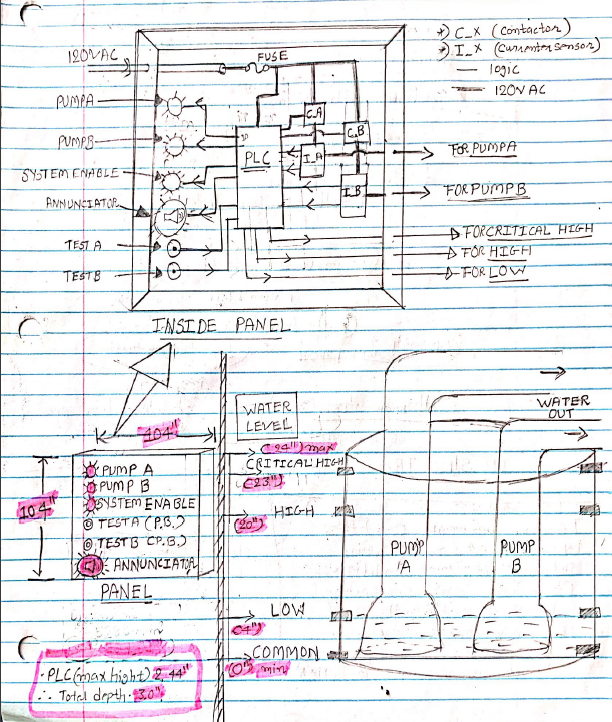
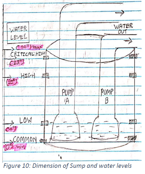
In this project, water levels were created by simply connecting conductive electrodes at a different height in the sump. There are three primary water levels: LOW level, HIGH level, and CRITICAL HIGH level. As mentioned in Figure 10: Dimension of Sump and water levels the LOW level at 4”, the HIGH level at 20”, and CRITICAL HIGH level at 23” height from the bottom of the sump. PLC using these water levels as input, and according to the program (ladder logic), turns on or off with the help of contractors. Apart from these levels, an electrode is connected at the bottom of the sump (named COMMON), 24 VDC from PLC. The primary function of the LOW level is to protect pumps from dry run conditions. LOW level is an input for PLC, which acts as a stop switch (concept of stop switch) logic to pump A and pump B (See Appendix E: Code, network 5 & 13). When the water reaches below low level, both pumps will be turned off, and pumps would always be at some water level. A HIGH level will allow PLC to turn ON contactor A (pump A) with 2.5 Status Indicators (Q0.0, Q0.1) (pump A status indicator). If water reaches a CRITICAL HIGH level, then PLC turns ON pump B and pump A (Pump A not ON by High level). At this level, both pumps forcing out water from the sump.
Reset
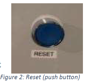
This input (Figure 2: Reset (push button)) introduced for two main reasons: 1. Once the annunciator starts emitting noise and flashing light, inform the user about a critical situation. The user is now well informed about this situation, and if the user wants to stop the annunciator, press the RESET button for 5 seconds. 2. When current sensors detect fault (underload/overload), then PLC turns OFF that load (pump A or pump B), and 2.5 Status Indicators (Q0.0, Q0.1) start flashing (Fault mode). Now, the user wants to check whether the fault is apparent or not to make sure that they press the REST button for a moment.
Current Sensors
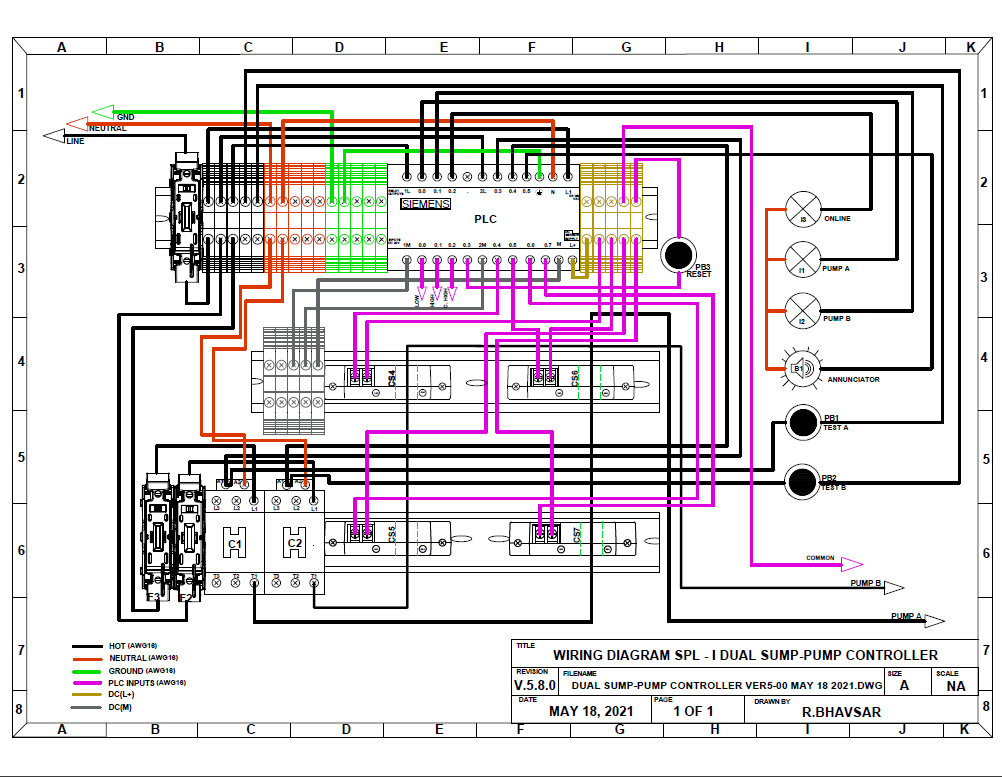
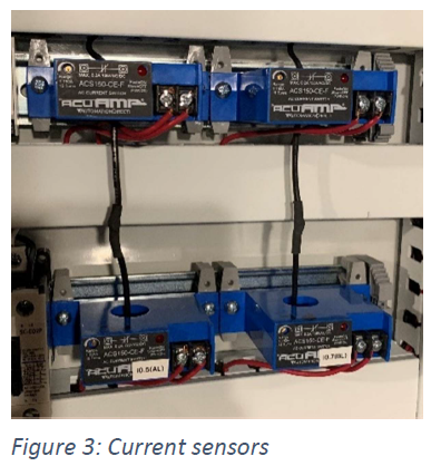
These sensors connected to the PLC input terminal and hot wire of load (pump A and pump B) pass through the hole on it as shown in (Appendix C: Wiring Diagram), and The working principle of these sensors is based on a current transformer (C.T.). These sensors (Figure 3: Current sensors) protect load connected across contactor from overload and underload by opening contactor terminals. The sensor works only when the contactor is ON. These sensors’ trip points would be adjustable (if in future user change pump). Inputs I0.4 and I0.5 of PLC save pump A (load connected across contactor A) from overload and underload, respectively. Also, Inputs I0.6 and I0.7 of PLC save pump B (load connected across contactor B) from overload and underload, respectively.
Status Indicators
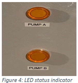
Indicate the pump's current operation (or status), and it is attached to the front of the panel. Using single LED indicators (ECX1053-120, ECX1052-120), this project saves multiple input terminals and a program line. Yellow color LED light (has supply voltage 120 VAC) shows ongoing PUMP A and PUMP B operation. During OFF (Figure 4: LED status indicator) mode, this status indicator stays off. However, during ON mode, light laminate with full lamination, and during FAULT (overload /underload), this indicator starts flashing [2].
Technical Description
Physical and user interaction description
It is a fully automatic controller which required the least amount of user interference. The regular operation is performed according to water levels detected by PLC. The operation order could be more transparent by looking Figure 9: Front side of the panel, the COMMON electrode located at the bottom of the sump, 24V D.C. from PLC and LOW level fixed at around 4 inches of height from the bottom of the sump. The HIGH and CRITICAL HIGH levels were located about 20 inches and 24 inches, respectively. When the sump starts filling with water and reaches a HIGH level, it will turn on the PUMP A and its indicator if the input water force is more than PUMP A’s troughing capacity, the water level increases. Once it reaches the CRITICAL HIGH level, PUMP B will be additionally joined to complete operation. In addition to this, if water goes above CRITICAL HIGH level or stays there for more than 2 minutes, the user will be notified by ANNUNCIATOR. When water starts decreasing below the HIGH level, PUMP B will be stopped, and PUMP A works standalone. Once this water level reaches below the LOW level, PUMP A will be destroyed, and there is some amount of water stays in the sump to protect pumps from dry-run conditions. There is a RESET button on the front side (Figure 9: Front side of the panel) of the board, which stops the annunciator (press for 5 seconds when it’s ON) and reset Figure 10: Dimension of Sump and water levels Figure 9: Front side of the panel the load (after clearing the fault, press it for a moment). TEST A and TEST B will allow users to check the pump’s functionality and help users while replacing the pump.
Electrical/Electronics description
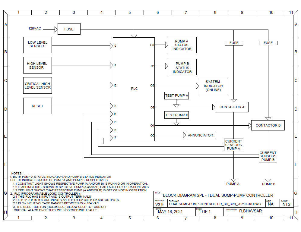
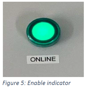
In this project, seven segments were used (located on the front panel), which works as user interference. Three of them are momentary push button (Appendix G: Datasheets), where 2 TEST button connects 120VAC supply and pump (there is no interference of PLC), and a RESET button is working as an input (I0.3) of PLC. Moreover, as mentioned in the block diagram (Appendix B: Block Diagram), annunciator (O0.5) and three other indicators (PUMP A (O0.0), PUMP B (O0.1), ONLINE (O0.2)) are connected to output PLC which is 120VAC input supply rated.
No specific sensors used in this project measure water level; the conductivity of water is used to do it. The inputs I0.0, I0.1, and I0.2 are the water levels LOW, HIGH, and CRITICAL HIGH defined in this project. All three water levels connected at different heights using conductive wire and at the very bottom of sump COMMON are located, which is +24VDC come from PLC. As the number of waters increases in the sump, it works as a conductive layer for this water level and connects electrically. So as the amount of conductive material is more, it gives better results.
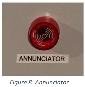
Contactors (2.8 Contactor (A & B))are the medium of the device between PLC and pumps. This contractor works according to the PLC ladder logic and can be operated with TEST buttons (2.7 Test Pump (A & B)). TEST button provides a 120VAC supply if it is pressed and hold. The PLC logic is defined to operate PUMP A at the HIGH level of water and both pumps at the CRITICAL HIGH station. When the water level decreases and reaches below HIGH level, PLC will turn OFF PUMP B, and the remaining operation is done with PUMPA. Once the water level goes below the LOW level, both pumps' safety stops and keeps some water in the sump. Annunciator (2.9 Annunciator (Q0.5)) is the device that informs the user about a critical situation in which water stays above the CRITICAL HIGH level for more than 2 minutes. The name annunciator has been given to it because of its functionality, flashing light, and making noise. In addition, the system enables the indicator to show PLC status, either ON or OFF. The logic behind both functions has been defined in the code. Network 17 offers the reason behind the ONLINE (2.6 System Enable Indicator (Q0.2)) indicator and network 18 to 22 defined for annunciator.
The output of the current sensors goes to PLC input which is normally closed. Four sensors connected in the system protect both pumps from overload (A.H. and B.H.) and under load (A.L and B.L). The working phenomenon behind these sensors is the same as the current transformer, which works on EMF principal. According to set current tripping points, when these sensors detect the threshold current, send a signal to PLC, and according to the program, PLC controls contactors of the pump.
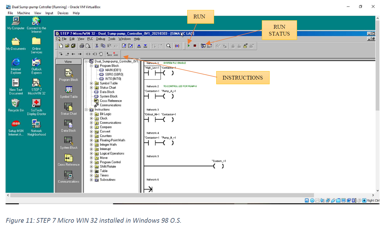
Analysis or Software description
For programming as an IDE (Integrated development environment) project, STEP 7 Micro WIN 32 has been used, which works only in Windows 98 Operating System device. To install windows 98 in the latest system, one should download and install Oracle V.M. Virtual Box manager (https://www.virtualbox.org/wiki/Downloads). It allows working on windows 98 in the current O.S. Once all these steps are done, the windows will look like Figure 11: STEP 7 Micro WIN 32 installed in Windows 98 O.S. (also shows the first version of ladder logic). Additionally, suppose there is no DB-9 plug available in someone’s computer. In that case, one should buy a USB to the serial port cable, which is available on this site .The code for this project is given in Appendix E: Code section. All the rungs and instructions defined and the table mentioned in this section show data of inputs and output of PLC. Network 17 in the program stands for system enable indicator, which states that the siemens ladder logic does not use coil instruction without any input instruction. There is no Status file available like Allen breadly (RSlogic), so to blink, the LED light program was defined in three lines. In this program, Network 6,7, and 8 to flash pump A indicator and Network 14, 16, and 17 are determined to blink pump B. Network 1 to 5 controllers the PUMP A, Network 9 to 13 stands for PUMP B Network 18 to 22 define for annunciator.
Testing and Results
There are two tests performed on this project. The first is the Current sensors calibration test, and
the second is the RESET function test.
The first test has been performed to define the bracket for the pump. The frame means overload
current limit and underload current limit. For example, the
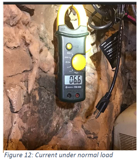
pump currently connected in the system consumes 6.7A
(IFL) current under normal condition (operation in water,
Figure 12: Current under normal load). However, when the
pump is sucking air, it consumes 7.20A (INL)current, and
when an object stuck in the shaft and shaft stops moving
(block rotor current), the pump consumes 9.02A (IBL). By
observing this result, it can be concluded that if the pump
runs under the limit of 6A to 7.10A would be protected from
electrical fault all time. So, this pump bracket is 6A to
7.10A.
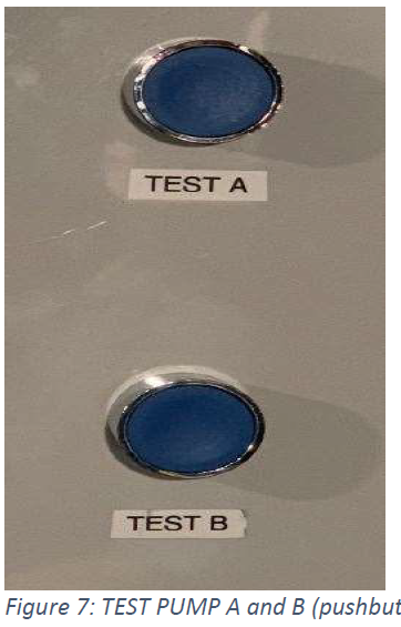
To caliber this bracket on this system, one does not need a multimeter; plug in the pump and
press the TEST (Figure 7: TEST PUMP A and B (pushbutton))button for that pump and hold it. Then,
RUN
STATUS
RUN
INSTRUCTIONS
Figure 12: Current under normal load
9
open the panel and observe the input signal on PLC. Considering calibration for PUMPA, on
A.H. (pump A upper limit), turn POT clockwise until light doesn’t show up on the I0.4 indicator,
and when the light glows, turn another half in the same direction. For lower limit, Adjust POT on
A.L. (pump A lower) and rotate counter-clockwise until light OFF on I0.5 on PLC. Once the I0.5
indicator turns off, turn another half in the same direction. Now, current sensors are calibrated
and ready for operation, release the TEST button and close the enclosure.
The second test performed on RESET functionality, the RESET (2.3 Reset (I0.3)) button designed
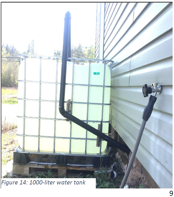
to perform two tasks. The first task is to stop the annunciator. To accomplish this, pumps were
disconnected from the receptacle then water keeps above the critical high-level surface using an
external water tank (Figure 14: 1000-liter water tank). While this process time has been recorded for
two minutes after two minutes annunciator starts, and to stop it press the RESET button for five
seconds. Then, wait for another 2 minutes to make sure the annunciator doesn’t turn on.
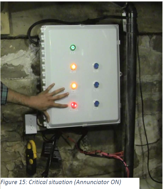
The second part of this test required
the same tools as the first part. To do
this, fill out the sump with the help of
an external water tank (Figure 14:
1000-liter water tank). After this,
plugin nominal load, pump, and press
the reset button for a moment, and the
Figure 14: 1000-Figure 15: Critical situation (Annunciator ON) liter water tank
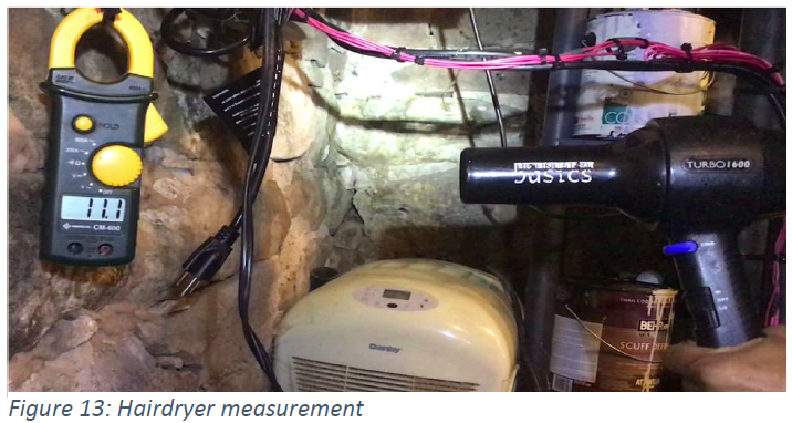
Figure 13: Hairdryer measurement
10
system, will accept this calibrated load. Repeat these steps for PUMP A) and make sure water
remains until CRITICAL HIGH level. At this moment, both pumps start functioning. Next,
remove the plug of PUMP B to perform the test in no-load condition. Now, current sensors
detect this fault, and PLC will turn off the supply for PUMP B. The pump indicator starts
blinking, and to continue with this operation, press the RESET button for a moment. If there is a
fault system will not allow operating this pump. Also, perform this with the help of a hairdryer
consuming 11.1 A (Overload condition, Figure 13: Hairdryer measurement). After this, plugin
nominal load, pump, and press the reset button for a moment, and the system, will accept this
calibrated load. Repeat these steps for PUMP A.
Conclusion
Figures

References
[2] Kurt_Aust, "Win98_SE_step by step," 10 Jan 2014. [Online]. Available: https://forums.virtualbox.org/viewtopic.php?f=28&t=59559. [Accessed 10 Jan 2014].
[3] Winworldpc.com, "Windows 98 seond edition," Winworld, May 04 1999. [Online]. Available: https://winworldpc.com/product/windows-98/98-second-edition. [Accessed May 04 1999].
[4] RDPetruska, "Serial adepter on Win 98," 16 Nov. 2016. [Online]. Available: https://communities.vmware.com/t5/VMware-Workstation-Pro/serial-adapter-on-Win-98/tdp/ 945290. [Accessed 16 Nov. 2016].
[5] S. A. Mousa, "#19/S7 200 Siemens/blinking ض ", 21 وم Feb. 2018. [Online]. Available: https://www.youtube.com/watch?v=eXs2cPNoEG0. [Accessed 21 Feb. 2018].
[6] scitechdd.wordpress, "SciTech Display Doctor 7 beta," SciTech Display Doctor , 30 Oct. 2012. [Online]. Available: https://scitechdd.wordpress.com/2012/10/30/4/. [Accessed 15 Mar. 2021].
[7] J. L. Schum, "Making wiring diagram," in Locksmithing and Electronic Security Wiring Diagram, New York, McGraw-Hill, 2003, pp. 41-54.
Contact
Email:
rohan.1290@gmail.com
Call:
+1 506-381-9490